How to Use a Multimeter on a Phone Motherboard
17 November 2026 · LightspeedTools team
Short answer: On a phone motherboard you mainly use four multimeter modes: continuity, diode mode, resistance and DC volts. Diode, resistance and continuity checks are done with the board unpowered and the battery disconnected, and the readings only mean something when compared with a known-good board or a schematic or board-view reference. Fine probes, a steady hand and a consistent probe convention matter more than the meter's price.
Why a multimeter is still the core board tool
Thermal cameras and current-limited power supplies get a lot of attention, but most board diagnosis still comes down to one question: is this line where it should be? A multimeter answers that for a fuse, a filter, a coil, a capacitor, a data line or a whole power rail. Used properly, it tells you where to look before any heat touches the board.
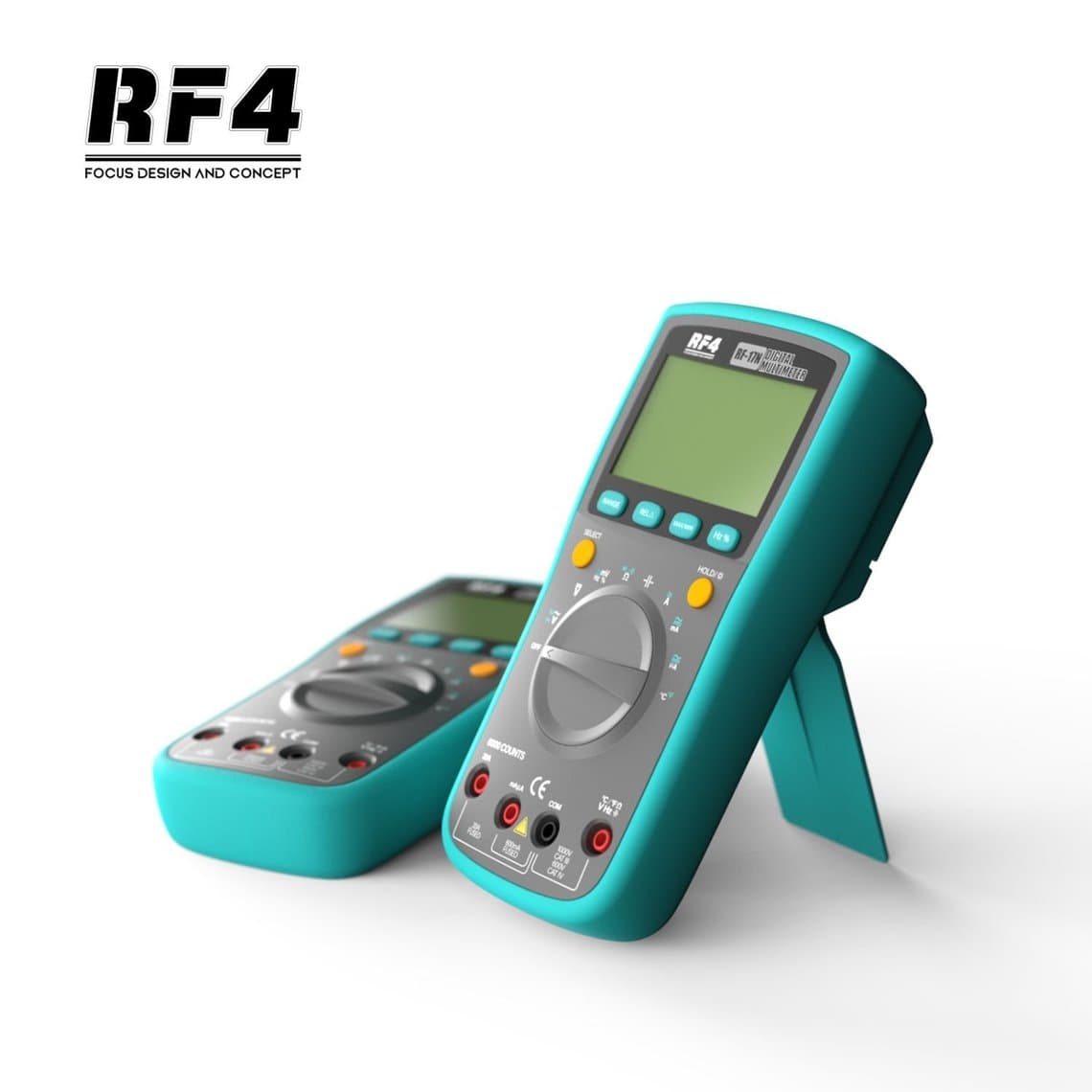
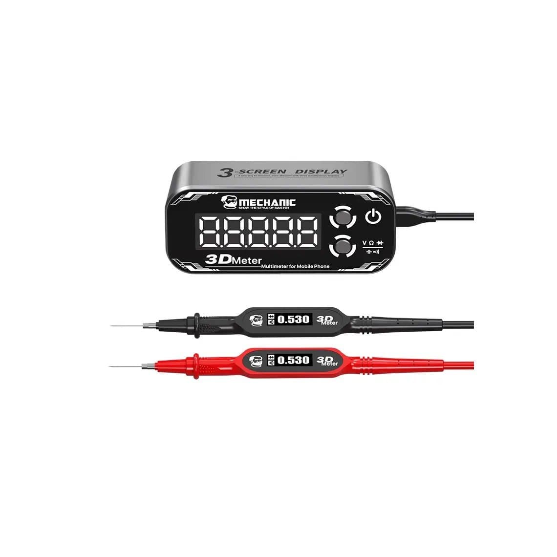
Any decent digital meter will do the job. Auto-ranging meters such as the RF4 RF-17N or the Sunshine DT-17N save time switching ranges, and the 2UUL MT30 is built around bench repair use. Some meters, like the Mechanic 3D Meter Detective V3.0, are aimed specifically at phone boards. Check the product page for each model's exact functions and diode mode range. The full selection is in our multimeter category.
The four modes and what each one tells you
| Mode | Board state | Typical use on a phone board |
|---|---|---|
| Continuity (beeper) | Unpowered | Fuses, filters, flex traces, broken tracks, connector pins to their destination |
| Diode mode | Unpowered | Measuring test points and connector pins to ground, finding shorts and open lines |
| Resistance (ohms) | Unpowered | Rail resistance to ground, resistors, partial shorts, coil checks |
| DC volts | Powered | Checking whether a rail or signal is present when the board is on the power supply |
Continuity
The meter beeps below a low resistance threshold. It is fast for checking whether two points are connected, such as both ends of a fuse or a pin on the charge port connector and the pad it should reach. It is not useful for judging a short, because many healthy rails also beep briefly to ground while their capacitors charge, and the beep threshold varies between meters.
Diode mode
In diode mode the meter pushes a small, fixed current and shows the voltage drop it sees. On a phone board you measure a test point against ground, and the circuitry behind that point (protection diodes, IC inputs) produces a characteristic reading. A reading near zero suggests a short to ground; an open reading (OL) on a line that should show a value suggests a broken trace, a missing pad or an open component. This is the most used mode in phone board work, because it gives repeatable numbers that can be compared point by point.
Resistance
Resistance mode tells you how many ohms sit between two points. It is good for confirming a resistor's value off the board, measuring a rail to ground when diode mode is ambiguous, and spotting a partial short that reads low but not zero. Readings on a board are affected by parallel components, so an in-circuit resistor rarely reads its marked value.
DC volts
This is the only mode used with the board powered. With the board on a DC power supply or a charged battery, you check whether a rail comes up when the phone is triggered on. Probe carefully: slipping between two pads on a live board can short a rail and do real damage.
Unpowered means unpowered
Diode, resistance and continuity modes feed their own small current into the circuit. If the board is powered, readings are meaningless and the meter or board can be damaged. Before any of these measurements:
- Disconnect the battery connector and any power supply cable.
- Disconnect the screen and other flexes if you want readings of the board alone; attached parts can change values.
- Wait a moment for large capacitors on the main rail to discharge.
- Work on a grounded ESD mat with a wrist strap.
Probe convention in diode mode
When measuring a phone board in diode mode, one probe goes on ground and the other on the test point. Which probe goes where changes the number, so you must use the same orientation as the reference you compare against.
The most widely used convention in phone board references is red probe on ground and black probe on the test point. This is sometimes called a reverse or "to-ground" reading, and many board-view diode values are recorded this way. Some technicians and some references use the opposite orientation, black on ground and red on the point. Neither is wrong as long as you are consistent; the mistake is mixing them. If a board-view or schematic note states the method, follow it. If it does not, measure a few points on a known-good board both ways and see which orientation matches the reference.
Good ground points are shield frames, large ground pads and the negative pad of the battery connector. Use the same ground point for a whole session.
Reference values: known-good boards, schematics and board view
There is no universal table of diode values that applies to every phone. Readings depend on the model, the board revision, the meter's test current and the probe convention. That is why this guide gives no numbers. The reliable references are:
- A known-good board of the same model. The best reference, measured with your own meter.
- Board-view software that lists typical diode readings for test points and connector pins on many models.
- Schematics that show which rail a point belongs to and what sits on it, so you can judge whether a low reading makes sense.
Treat published numbers as a guide, not an exact target. A reading that differs slightly from the reference is usually normal; a reading near zero, OL where a value is expected, or a clear mismatch between matching pins on two similar lines is worth investigating.
Fine probes make or break board work
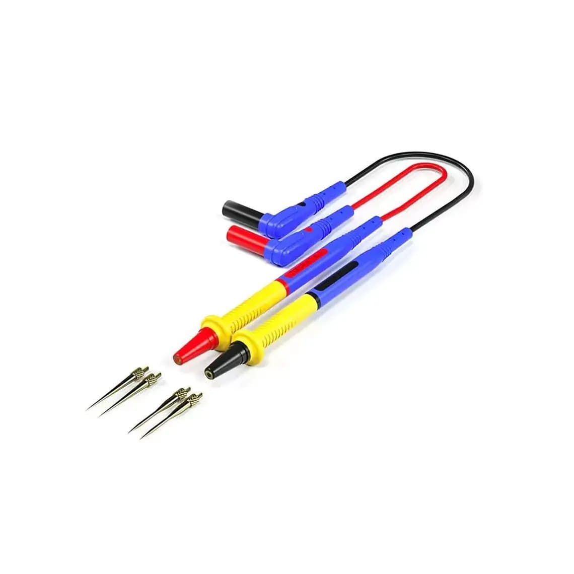
Standard meter probes are too broad for phone boards. Components can be a fraction of a millimetre across, and a thick tip bridges pads or slips onto the wrong one. Practical options:
- Fine replacement probes such as the 2UUL MT02 fine-tip test probes or the JCID ZF003/ZF005 ultra-fine probe kit.
- Needle tips like the 2UUL MT03 FinePoint titanium tip or the Mechanic 0.1mm stainless steel probe, which can reach connector pins and small capacitor pads.
- Tweezer probes for measuring small loose components off the board.
Measure under a microscope. You will see exactly where the tip lands and avoid scratching the solder mask.
Testing common components
Fuses
Phone fuses sit on lines such as the charge port supply and backlight circuits. Use continuity or low resistance across both ends with the board unpowered. A healthy fuse reads close to zero ohms; an open reading means it has blown. A blown fuse usually means something downstream is shorted, so check the line beyond it before replacing.
Filters and coils
Data and signal filters and power coils (inductors) should show continuity end to end. An open filter on a data or display line or an open coil on a power rail is a common fault after a drop or liquid damage. Coils on PMIC outputs can also be used as convenient test points for their rail in diode mode.
Capacitors
You cannot reliably check a capacitor's value in circuit with a basic meter. What you can check is whether it is shorted: measure across it in diode or resistance mode. Near zero means the rail is shorted, but every capacitor on that rail will show the same reading because they are in parallel. Finding which one is faulty needs a heat method, covered in our guide to phone short circuit repair, or removal one at a time.
Connector pins
Measuring each pin of a screen, battery or charge port connector to ground and comparing with a reference is one of the fastest ways to find a damaged line. Compare pins that should match, such as pairs of data lines, as well as the reference.
Rails with the board powered
Switch to DC volts, connect the board to the supply, trigger it on and check that each expected rail appears. A missing rail points to the PMIC or the circuit feeding it. For a full no-power diagnostic flow, see phone not turning on: board-level diagnosis. If a rail is present but something is overheating, a thermal camera is the next tool.
Common mistakes
- Measuring diode or resistance with the battery still connected.
- Mixing probe orientation between your readings and the reference.
- Comparing against values from a different model or board revision.
- Calling a rail shorted because continuity beeped briefly while capacitors charged.
- Using broad stock probes and bridging two pads.
- Leaving the meter in a current range and then probing a live rail.
- Replacing a blown fuse without finding what blew it.
Safety
- Disconnect the battery before unpowered checks and before any soldering or hot air work. Never pierce or bend a lithium battery while probing.
- Use ESD protection; phone ICs are sensitive to static.
- On a powered board, set a sensible current limit on the supply so a probe slip does less damage.
- Check your meter's lead sockets match the mode before measuring voltage.
Questions
Which multimeter setting is used most for phone repair?
Diode mode. It gives repeatable readings of test points and connector pins against ground, which you compare with a known-good board or board-view values to find shorts and open lines.
Should the battery be connected when testing a phone motherboard?
Not for diode, resistance or continuity checks. Disconnect the battery and power supply first. Only DC voltage checks are done with the board powered.
Which probe goes to ground in diode mode on a phone board?
Many phone references use red on ground and black on the test point, while others use the reverse. Use whichever orientation your reference values were taken with, and stay consistent through the whole job.
How do I know what reading a test point should give?
Compare with the same point on a known-good board of the same model, or use board-view software that lists typical readings. Schematics show which rail the point is on, which helps you judge whether a reading is plausible.
A good meter and the right probes pay back on every board job. Browse our multimeters and probes, all tested before shipping from Shenzhen by DHL, FedEx or UPS. Repair shops can open a wholesale account, with wholesale prices unlocking after $500 of purchases, and reorder by SKU or CSV through Quick Order.