Microscope Camera Guide: C-Mount Cameras, Lenses and Lights
17 November 2026 · LightspeedTools team
Short answer: A microscope camera mounts on the trinocular port of a stereo microscope, usually through a C-mount adapter, and sends a live image to a monitor or computer. For live soldering, choose a camera with HDMI output and a smooth frame rate such as 60FPS, because low latency matters more than headline megapixels. Add an auxiliary objective lens to change magnification and working distance, and good LED lighting to make the image usable.
If you are still choosing the microscope itself, start with our guide to the best microscope for mobile repairing. This article assumes you already have a stereo microscope on the bench and want to get more out of it: a camera, a screen, extra lenses, better light and a way to record your work.
How a microscope camera connects
Most repair-bench stereo microscopes come in two optical layouts. A binocular head has two eyepieces only. A trinocular head adds a third port, normally on top, that sends part of the image up to a camera. If your microscope is binocular, you cannot simply add a C-mount camera; you need a trinocular head or a different setup.
The usual chain looks like this:
- Trinocular port on the microscope head.
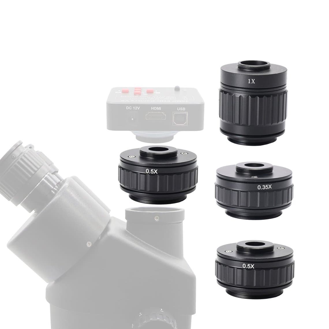
- C-mount adapter that fits the port and matches the camera thread. A C-mount focus adapter lets you adjust focus at the camera so the screen image and the eyepiece image are sharp at the same time.
- Camera with a C-mount thread.
- Output to a monitor over HDMI, or to a computer over USB.
Port diameters and adapter sizes vary by microscope brand and model, so check the port size before ordering an adapter. Some adapters also include a reduction lens that changes how much of the field the sensor sees. If the screen shows a dark circle around the image (vignetting), or a much smaller area than the eyepieces, the adapter and sensor size are not well matched.
HDMI vs USB output
This is the first real decision, and it depends on what you will do with the image.
| Output | Best for | Watch out for |
|---|---|---|
| HDMI to a monitor | Live soldering and rework while watching the screen; no computer needed | Recording usually goes to an SD card or the camera's own storage, depending on the model |
| USB to a computer | Capturing stills and video straight into software, measurements, sharing on calls | Lag depends on the computer, cable and software; check before relying on it for live work |
| HDMI + USB in one camera | Benches that need both: a live monitor plus files on a PC | Confirm which features work on each output for that model |
| Wi-Fi or built-in display | Teaching, showing customers, quick inspection | Wireless links can add delay; less suited to fine soldering |
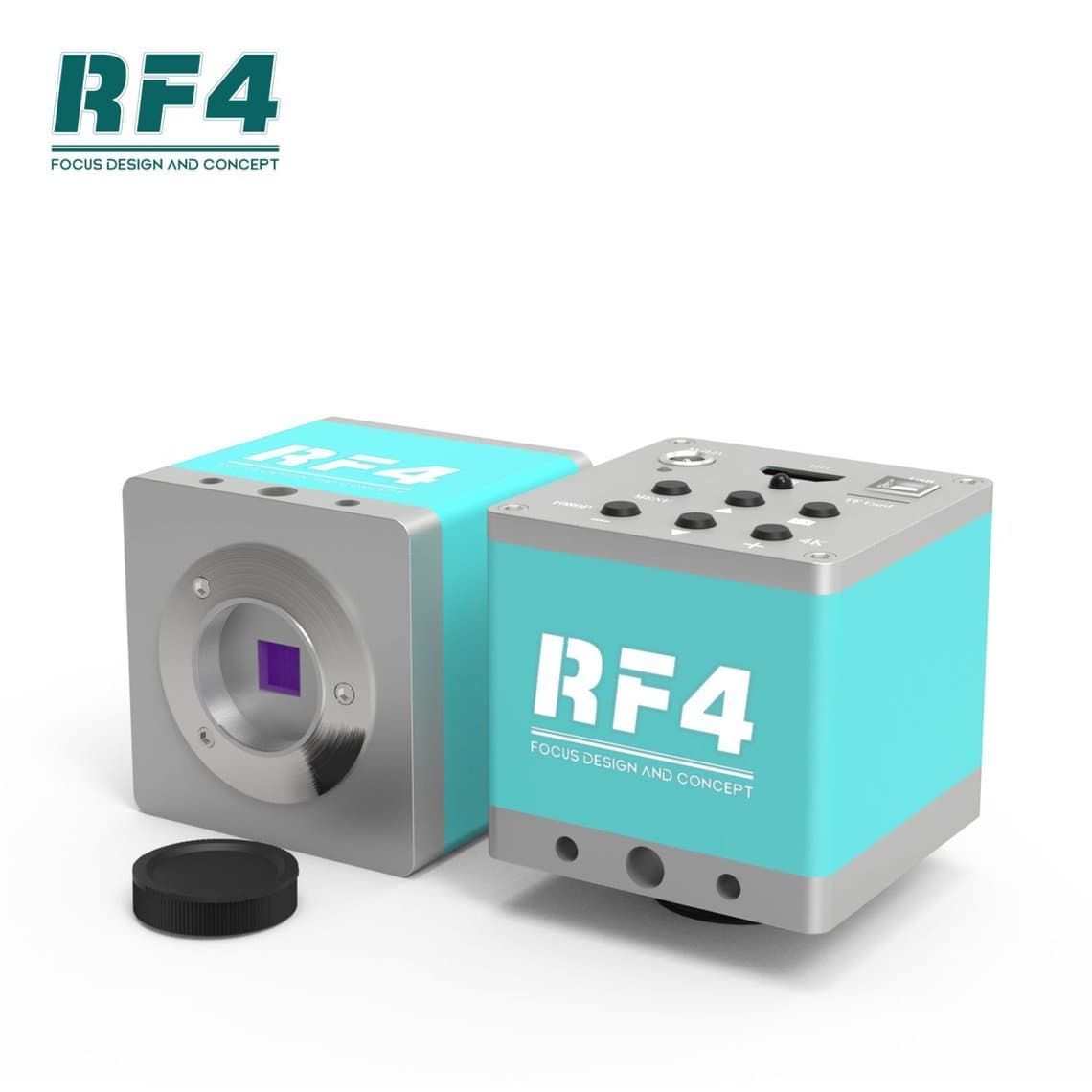
Many shops pick a camera that does both. The RF4 4KC1 HDMI/USB industrial microscope camera and the RF4 RF-2KC3 with HDMI and USB Type-C are examples of that dual-output approach. If you only want a screen on the bench, an HDMI-only camera such as the RF4 2KC2 1080P 60FPS HDMI camera keeps things simple.
Resolution, frame rate and latency
Camera titles are full of numbers: 14MP, 34MP, 48MP, 2K, 4K, 8K. These usually describe the still-image or sensor capability. What you see on the monitor during live work is limited by the video output, which is often 1080P, and by the frame rate.
- Megapixels help with still photos you crop or zoom later. They do little for live soldering if the video stream is 1080P.
- Video resolution (1080P, 2K, 4K) is what the monitor actually shows. A 4K stream only pays off on a 4K monitor.
- Frame rate is how smooth the image moves. 60FPS is noticeably smoother than 30FPS when you move tweezers or an iron tip.
- Latency is the delay between your hand moving and the screen showing it. Even a short delay makes fine work feel clumsy, and it can lead to bridged pins or a slipped tip.
For soldering while looking at the screen, put frame rate and latency first. For documentation and close-up stills, higher resolution matters more. A practical rule: do precise work through the eyepieces, and use the screen for positioning, inspection and showing others, until you have confirmed your camera's delay feels natural.
Higher-resolution cameras sold for this work are labelled 4K, 8K or by large megapixel counts. Read each listing for the actual video output and frame rate rather than judging by the largest number in the title. You can compare options in microscope cameras.
Auxiliary objective lenses: magnification vs working distance
An auxiliary objective lens screws onto the bottom of the microscope body. It changes two things at once: total magnification and working distance (the gap between the lens and the board).
| Lens | Magnification | Working distance | Field of view | Typical use |
|---|---|---|---|---|
| 0.5X | Halved | Much longer | Wider | Room for a hot air handle, tall tools, whole-board overview |
| 0.65X to 0.75X | Reduced | Longer | Wider | A balance between room and detail |
| None (1X) | As designed | Standard | Standard | Most general board work |
| 2X | Doubled | Much shorter | Narrower | Very fine inspection of small pads and connectors |
The trade-off is real. A 0.5X lens gives you room to work under the microscope and see more of the board, but each detail looks smaller. A 2X lens shows tiny parts larger, but the lens sits closer to the board, leaving little space for an iron or hot air nozzle, and the depth of field becomes shallower. Image brightness can also drop at higher magnification, so lighting matters more.
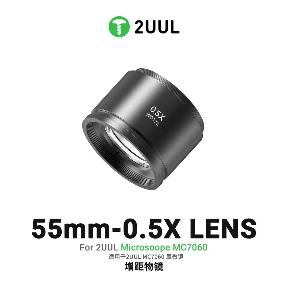
A 0.5X / 2X auxiliary objective (Barlow) lens covers both directions. Some lenses are made for one microscope family, such as the 2UUL MS05 0.5X lens for the MC7060, whose title states a 55mm thread and WD172. Check the thread size of your microscope before buying, and remember the lens affects the camera image as well as the eyepieces. Browse lenses and stands for more choices.
What "Barlow lens" means here
In astronomy, a Barlow lens multiplies magnification. On stereo microscopes the term is used loosely for any auxiliary objective that changes magnification, including ones that reduce it. When a listing says "Barlow lens", read the stated factor (0.5X, 0.7X, 2X) to know which way it works.
Lighting: ring lights and LED illumination
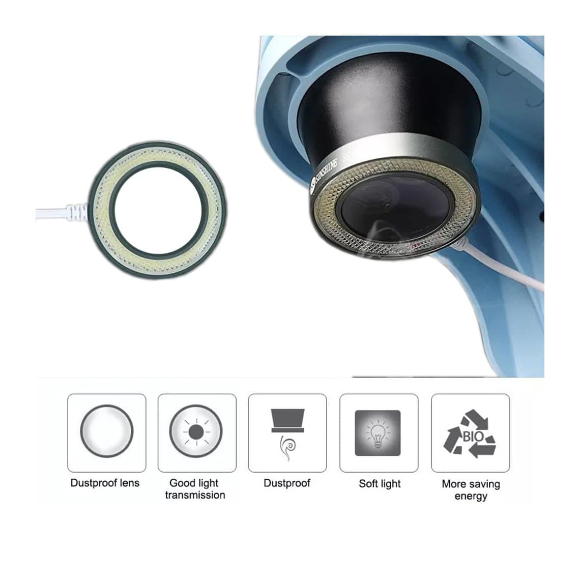
A camera needs more light than your eyes do. Poor light gives grainy, slow-looking video and false colours. Most repair benches use an LED ring light fitted around the objective lens.
- Even ring light works for general inspection and removes most shadows.
- Adjustable brightness helps avoid glare off shiny solder, shields and glossy chips.
- Angle matters. Some glare is useful to read the shape of a solder joint; too much hides cracks.
- Keep it clean. Flux smoke and dust settle on the light and lens. A dust-proof LED light is easier to keep clear on a busy bench.
If you are building a camera setup from scratch, kits exist that bundle the parts, such as the Sony IMX307 1080P HDMI/USB camera kit with lens and ring light. See LED ring lights for separate lights.
Monitors and mounting
Where the screen sits changes how comfortable long sessions are.
- Place the monitor at eye level and close to your line of sight to the board, so you do not twist your neck between screen and hands.
- Choose a size that fits the bench. A large screen far away is harder to use than a smaller one close by.
- Match monitor resolution to the camera output. A 1080P camera on a 4K screen gains nothing.
- Keep cables short and tidy, away from hot air and the iron.
- Make sure the microscope stand is stable. A camera adds weight to the head, and a wobbly boom arm shows every vibration on screen.
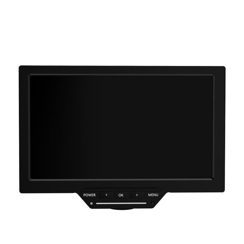
Some benches use a combined screen and camera unit instead of a trinocular microscope, such as the RF4 YS010W 10-inch Wi-Fi display with built-in camera. These suit inspection and customer demos. For fine soldering, most technicians still prefer a stereo microscope with true depth perception through the eyepieces.
Recording for customer proof and training
A camera turns the microscope into a record-keeping tool. Common uses in repair shops:
- Before-and-after photos of corrosion, a damaged connector or a lifted pad, to show the customer what was wrong.
- Proof of condition when a board arrives already damaged or previously repaired by someone else.
- Training clips so new staff can watch a reball or connector swap step by step. Pair them with a structured plan like micro soldering for beginners.
- Remote help, sharing a live view with a senior technician over a USB connection.
Keep customer data out of shots, name files by job number, and tell customers if you keep images of their devices.
Setup checklist
- Confirm your microscope has a trinocular port, and measure or look up the port size.
- Choose HDMI, USB or both based on live work versus recording.
- Fit a C-mount adapter that suits the port and the camera sensor size.
- Focus through the eyepieces first, then adjust the camera adapter until the screen matches (parfocal setup).
- Add an auxiliary lens only if you need more room or more detail, and refocus afterwards.
- Set the ring light brightness and white balance so solder looks silver, not yellow or blue.
- Test latency by moving tweezers under the lens before doing real work on screen.
Common mistakes
- Buying a C-mount camera for a binocular microscope with no camera port.
- Choosing by megapixels and ending up with a laggy live view.
- Fitting a 2X lens and then finding there is no room for the hot air nozzle.
- Skipping parfocal adjustment, so the eyepiece and screen are never sharp together.
- Leaving the lens and light uncovered near flux smoke; residue builds up and softens the image.
- Touching the board with a camera cable or metal stand while working; keep the bench ESD-safe and grounded.
Questions
Can I add a camera to any microscope?
A standard C-mount camera needs a trinocular port. On a binocular microscope there is no proper camera path, so you would need a trinocular head or a separate digital microscope. Check the port size before buying an adapter.
Is a 4K microscope camera worth it for phone repair?
It can be, for clear stills and on a 4K monitor. For live soldering, a smooth frame rate and low latency usually matter more than resolution. Check the video output and FPS for the specific model, not just the title number.
What does a 0.5X lens do on a stereo microscope?
It halves the magnification and increases working distance and field of view. You get more room for tools and see more of the board, but small parts appear smaller. Refocus after fitting it.
Why is my microscope camera image dark or ringed?
Common causes are weak lighting, a mismatch between the adapter and the camera sensor size, or a high auxiliary lens factor. Turn up or reposition the ring light, check the adapter type, and clean the lens and light.
Browse all microscope accessories or the full microscopes range to build out your bench. Shops buying for several benches can open wholesale pricing, and repeat orders are fastest through Quick Order by SKU or CSV.