How to Repair a Ripped-Off Solder Pad with Jumper Wire
17 November 2026 · LightspeedTools team
Short answer: To repair a ripped-off solder pad, first find out under a microscope which line the pad belongs to, using the schematic or boardview. If the pad was not connected to anything, you can often leave it. If it was, either expose the trace next to it by scraping off the solder mask, or run a thin jumper wire from the component to the nearest point on the same line, then fix it in place with UV solder mask and test continuity with a multimeter.
A ripped pad is one of the most common setbacks in board repair. It often happens while removing an IC or a connector. The good news is that most ripped pads can be repaired reliably with a jumper wire and some patience. This guide covers why pads come off, how to judge the damage, the three main repair options, choosing and fitting jumper wire, sealing the repair, and the mistakes that cause a repair to fail later.
How solder pads get ripped
A pad is a thin layer of copper bonded to the board. Once it has been heated many times, or pulled with force, the bond fails and the copper lifts away, sometimes taking part of the trace with it. The usual causes are:
- Lifting a chip before all the solder has melted. If one corner is still solid, the pad stays on the ball instead of the board. Underfilled chips are especially risky.
- Not enough flux. Dry solder melts unevenly and grips pads harder. Fresh flux helps heat spread and lets parts release cleanly.
- Too much heat for too long. Repeated heating weakens the adhesive under the copper.
- Prying connectors or shields. Levering a connector off before the solder flows tears the pads under it.
- Scraping too hard when cleaning. A solder wick dragged across a pad, or a blade pressed too firmly, can lift copper.
- Corrosion. Liquid damage eats into copper, so pads come off with very little force.
Most of these are about technique. Our micro soldering for beginners guide covers heat control and flux use in more depth, and how to reball a BGA chip explains safe chip removal.
Assess the damage under a microscope
Do not reach for wire yet. First look closely at what is left. A stereo microscope is essential here, because pads on phone boards are often smaller than the tip of a pin.
- Clean the area. Remove old flux and debris with isopropyl alcohol so you can see the copper clearly.
- Identify the pad. Use the schematic or boardview to find out which signal or power line the pad belongs to. Note whether the pad is connected (has a trace or via) or is an unused pad.
- Check for a trace. Look for a thin copper line leading away from the pad under the solder mask. If part of the trace is still attached, that is your easiest connection point.
- Check for a via. Many BGA pads connect straight down through a via. If the via is still visible in the pad hole, you may be able to connect to it directly.
- Find the nearest point on the same line. The boardview shows other components on that net, such as a capacitor or test point. These are your alternative connection points.
Many BGA chips have pads that are not connected to anything (sometimes marked NC in the schematic). If the ripped pad is one of these, it may need no repair at all. Confirm this in the schematic before deciding.
Repair options compared
| Option | When to use it | Difficulty |
|---|---|---|
| Leave it | The pad is not connected to any line | None, but confirm in the schematic |
| Scrape solder mask to expose the trace | The trace leading from the pad is intact and close to the part | Moderate |
| Jumper wire to the nearest point on the same line | The trace is damaged, hidden or too short to use | Moderate to high |
| Rebuild the pad | A BGA pad that needs a solder ball and has a usable via or trace | High |
Scraping solder mask to expose the trace
If the trace leaving the pad is still attached, you can scrape away the green or black solder mask over a short length of it. Use a sharp blade or fibre pen and work gently, removing the mask without cutting the copper. Once the copper shines, tin it lightly with flux and a small amount of solder. You now have a new pad to solder to, either directly or with a very short jumper.
Running a jumper wire
When the trace is gone, run a jumper from the component lead (or the new solder ball) to the nearest healthy point on the same line. That might be a capacitor pad, a test point or an exposed trace further along. Keep the jumper as short as possible.
Rebuilding a pad
For BGA chips, some techs rebuild a pad by placing a small piece of tinned wire or thin copper where the pad was, connecting it to the via or trace, and fixing it with UV solder mask so only the top is exposed. The chip then sits on it like a normal pad. This takes practice and the new pad must be level with its neighbours, so it is usually reserved for chips where a jumper cannot reach the right ball.
Choosing jumper wire
Jumper wire for phone boards is very fine copper or silver-plated wire, often with a thin enamel or insulation coating. The main choices:
| Type | Strengths | Watch out for |
|---|---|---|
| Enamelled ultra-thin wire | Very fine, insulated by the coating, good for BGA pads and tight spaces | The enamel must be removed or burned off at the ends before it will take solder |
| Insulated soft wire | Flexible, easier to route around parts, insulation prevents shorts | Thicker, so less suited to the smallest pads |
| Bare silver-plated wire | Takes solder easily, good for short links | No insulation; must be kept clear of other pads and sealed |
For example, the B&R 0.009 mm silver jumper wire and the 0.01 / 0.02 mm fly-line jumper wire suit very small pads, such as fingerprint and BGA lines. For longer or more flexible routes, the 2UUL FX-002S ultrasoft jumper wire is easier to bend around components. Match the wire thickness to the line: data lines can use very thin wire, but power lines carrying more current need thicker wire or several strands. Browse the full range in our jumper wire category.
Step by step: fitting a jumper wire
- Prepare both ends. Clean and flux the component lead or pad and the target point. Tin them with a small amount of solder.
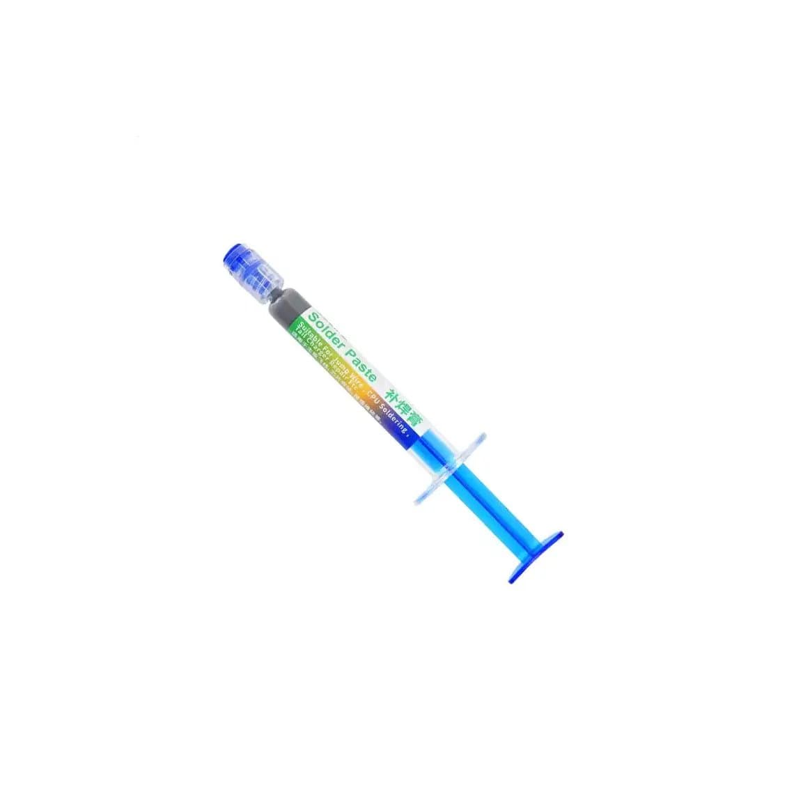
- Tin the wire. Cut a piece a little longer than needed. If it is enamelled, remove the coating at the tip with a hot iron and solder, or scrape it gently. Tin both ends. A dedicated jumper-wire paste such as Relife RL-405 solder paste helps the tiny joints flow.
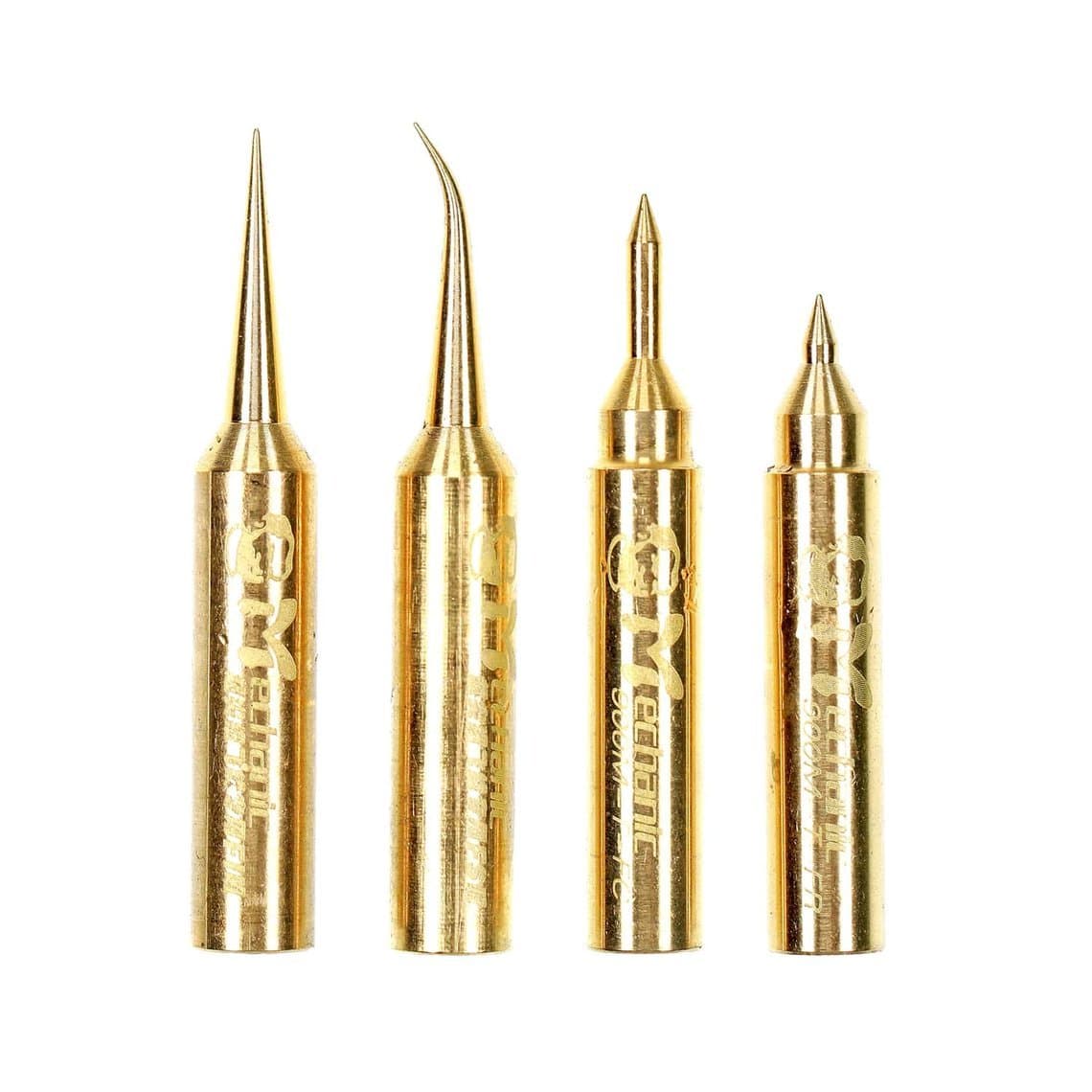
- Use a fine tip. A sharp, thin tip like the Mechanic 900M-T jumper wire tip or the RELIFE 210 tip with ultra-sharp needles lets you touch one point without disturbing the parts beside it.
- Solder the first end. Hold the wire with fine tweezers, place it on the first point and touch it with the iron for a moment.
- Route the wire. Lay it flat along the board, away from other pads and shields, with gentle curves rather than sharp bends. Keep it short and avoid crossing other lines where you can.
- Solder the second end and trim any excess wire with a sharp blade.
- Check under the microscope for solder bridges or stray strands touching neighbouring pads.
Securing the repair with UV solder mask
An unsecured jumper can lift when the board flexes, when a shield is refitted or during the next heat cycle. Sealing it with UV solder mask holds it in place and insulates it.
- Clean the area of flux residue so the mask bonds well.
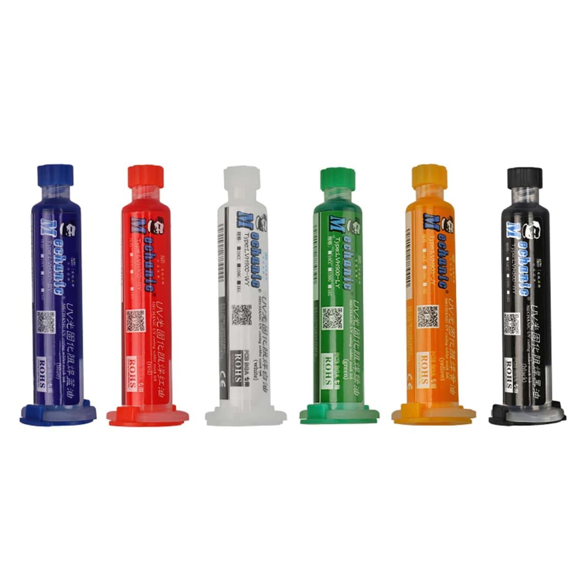
- Apply a thin layer of mask over the wire and joints with a fine needle. Syringes such as the 2UUL SC55 SuperDry UV solder mask or Mechanic UV solder mask ink make it easy to control the amount.
- Cure it with a UV curing lamp until it is hard. Follow the curing time on the product, and cure in thin layers rather than one thick one.
- If you rebuilt a pad, scrape the cured mask off the top of the pad only, so it can be soldered.
Keep mask off pads, connectors and parts that still need soldering, as cured mask is hard to remove. See all options in our UV solder mask category.
Testing continuity with a multimeter
Never assume a jumper is good because it looks good. With the board unpowered, set your multimeter to continuity or resistance and measure from the component end of the jumper to another point on the same line. You should see a very low reading. Then check from the jumper to ground and to the neighbouring lines to make sure there is no short. Diode-mode readings compared with a known good board are also useful. Our guide to using a multimeter on a phone motherboard explains these measurements step by step.
Common mistakes
- Jumping to the wrong line. Always confirm the net in the schematic or boardview; two pads next to each other can belong to completely different lines.
- Wire too thin for a power line. A thin wire on a high-current rail can heat up or burn open.
- Not removing enamel. The joint looks soldered but there is no electrical contact.
- Too much heat. Overheating while fitting the jumper lifts the next pad.
- Leaving the jumper unsecured. It works on the bench and fails after reassembly.
- Mask on pads you still need. Plan the order: solder first, mask last.
- Skipping the final test. Test continuity and check for shorts before you power the board.
Safety: disconnect the battery first and work on an ESD mat with a wrist strap.
Questions
Can a ripped solder pad be repaired?
Yes, in most cases. You can expose the trace next to it, run a jumper wire to another point on the same line, or rebuild the pad. If the pad was not connected to any line, it may not need repair at all.
What is the best wire for jumper repairs on phone boards?
Thin enamelled or silver-plated wire is the most common for signal lines and BGA pads. Use thicker wire or several strands for power lines that carry more current.
How do I find where to connect a jumper wire?
Use the schematic or boardview to identify the line the pad belongs to, then find the nearest component or test point on the same line. Measure continuity to confirm before you solder.
Do I need UV solder mask after a jumper repair?
It is strongly recommended. It holds the wire in place, insulates it from nearby parts and protects it from lifting during reassembly or later heating.
Find everything for pad and jumper repairs in our jumper wire and UV solder mask categories. All tools are tested before shipping from Shenzhen by DHL, FedEx or UPS. Repair shops can unlock wholesale prices through our wholesale programme and reorder by SKU or CSV with Quick Order.